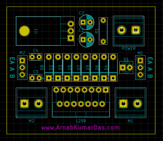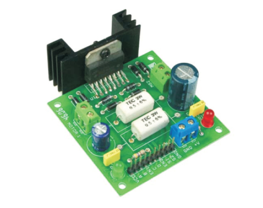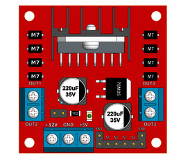

The 12V going into the motor driver comes from a voltage regulator set at 12V. The L298N motor driver was also obtained from the lab stockroom.īelow is our wiring diagram for the drivetrain. Initial qualititative testing proved that these motors would run fast enough and were powerful enough for the robot. These motors were chosen because of their high torque output.

We chose two Zheng ZGB37RG from the ME 210 lab stockroom to drive the wheels.

The two casters are mounted using 1/4" bolts and nuts to the chassis. A helical shaft coupler connects the wheel shaft to the motor shaft to account for any misalignments. The batteries are mounted to the chasses via velcro strips, the motor is mounted using motor mounts, and the wheels are supported on both sides to reduce the bending moment on the motor. driver: L298N driver power supply: + 5 V to + 35 V driver output current (max.).
#L298N MOTOR DRIVER CAD FULL#
A CAD rendering of the drivetrain is shown below.Īll components of the chassis are lasercut from 1/4" thick Duron sheets and glued together. This module allows full control of two DC motors or one stepper motor. DistributorSKUStockMOQ1101001000RS Components3706953125 6.06 5.70 4.85 DigiKey49713955ND01 6.49 5.83 4.78 4.04Newark2 SKUs01 7.19 6.45 5. If you want to control the speed of motors, you need to remove the jumpers and connect them to PWM-enabled pins on Arduino.Our drivetrain consisted of two brushed DC motors each driving a scooter wheel, two casters for stability, and an L298N motor driver to control the motors. When this jumper is in place, the motor is enabled and spins at maximum speed. The module usually comes with a jumper on these pins. Speed Control Pins :ENA and ENB are used to turn the motors ON, OFF and control its speed.

Output Pins : The L298N motor driver’s output channels for the motor A and B are broken out to the edge of the module with two 3.5mm-pitch screw terminals.ĭirection Control Pins : The IN1 and IN2 pins control the direction of the motor A while IN3 and IN4 control the direction of the motor B. What is a website - Explanation Raspberry Pi - An Introduction. With L298N, you can control up to two dc motors or two pairs of different DC motors. Warning : if the motor power supply is greater than 12V, you should remove the jumper to avoid the on-board 5V regulator from getting damaged.Also DO NOT supply power to both the motor power supply input and 5V power supply input when jumper is in place. To control 16 servos at a time you can use the 16 channel 12-bit PWM servo motor driver.
#L298N MOTOR DRIVER CAD FREE#
Australian Stock and Warranty with Fast Free Shipping from our Sydney Warehouse. And they both sink to a common ground named ‘ GND ’. FREE SHIPPING available on Arduino 4 Wheel Drive Motor Driver Module. 6 MX1508 Mini Driver, Electronics Camera Photo Accessories Mini Mini DC Mini 6 Dual L298N Motor Chann Chann 6 MELIFE Pack MELIFE Pack L298N Driver. ' Vss ' is used for driving the logic circuitry which can be 5 to 7V. Power Supply : From ' Vs ' pin the H-Bridge gets its power for driving the motors which can be 5 to 35V. Our drivetrain consisted of two brushed DC motors each driving a scooter wheel, two casters for stability, and an L298N motor driver to control. L298N motor driver board module Description: L298N is a high voltage, high current motor driver chip. The L298N is a dual-channel H-Bridge motor driver capable of driving a 2x DC motors, making it ideal for building two-wheel robots. This leads to a change in the direction of the motor. H-Bridge – For controlling rotation direction: An H-Bridge circuit contains four switches with the motor at the center forming an H, closing two particular switches at the same time reverses the polarity of the voltage applied to the motor.
#L298N MOTOR DRIVER CAD SERIES#
PWM – For controlling speed: PWM is a technique where average value of the input voltage is adjusted by sending a series of On/OFF pulses, the average voltage is proportional to the width of the pulses known as Duty Cycle.The higher the duty cycle, the greater the average voltage applied to the dc motor this lead to the highest speed.


 0 kommentar(er)
